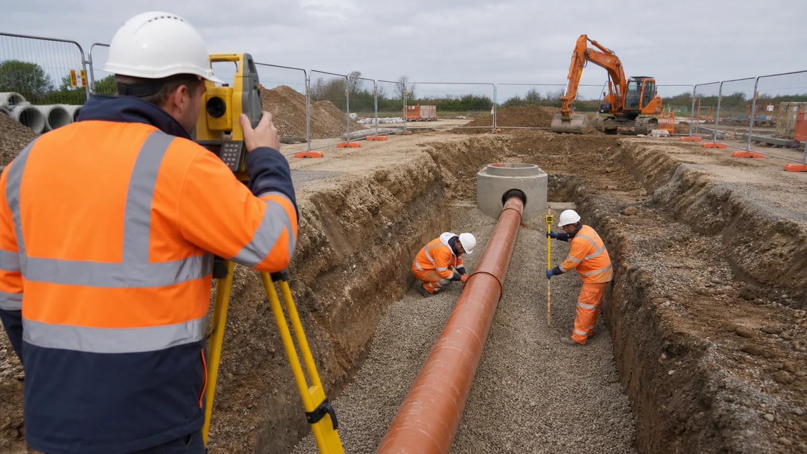
Drainage Run Checker: Pipe Gradients, Invert Levels & As-builts
Drainage Run Checker: How to Verify Pipe Gradients, Invert Levels, Cover and As-built Records
A practical guide for site engineers, drainage contractors and surveyors who need to check a drainage run before backfilling, handover or approval.
Open the free Drainage Run CheckerWhat is a drainage run checker?
A drainage run checker is a calculation and quality-control tool used to confirm that a pipe run has the correct direction of fall, gradient, invert levels and cover. The checker compares consecutive surveyed or designed points, identifies flat or adverse sections, highlights insufficient cover and produces a traceable schedule for review. A good checker does not replace hydraulic design; it verifies that the geometry entered or measured on site is internally consistent and meets the selected project criteria.
Underground drainage is unforgiving. Once a trench has been backfilled, correcting an incorrectly laid pipe can require excavation, road or slab removal, replacement bedding, repeat testing and new survey work. The direct cost can be significant, but programme delay, aborted follow-on work and commercial disputes are often more damaging. A short geometry check before acceptance is therefore one of the highest-value quality-control activities available to a site team.
The free Drainage Run Checker & As-built Pack on Site-Survey.co.uk is designed for this task. It accepts multiple manholes, inspection chambers or surveyed pipe points in a single run. For every adjacent pair it calculates pipe length, fall, gradient and slope, while also checking cover at each point. It then creates an editable schedule with PASS, REVIEW or FAIL flags, approximate quantities, checker notes and export controls for CSV and printable PDF reporting.
Why every drainage run should be checked
A drainage drawing may define chamber references, invert levels, pipe diameters and gradients, but the installed geometry can still differ from the design. Bedding may settle or be trimmed incorrectly. A chamber base may arrive at the wrong depth. A pipe socket can lift during connection. A clash with another service can force an unrecorded level change. Finished ground levels may also change after the drainage design was issued. Each difference can affect flow, cover or buildability.
Checking only the upstream and downstream chamber is not always enough. A long run may have the correct total fall while containing a local flat spot or backfall between intermediate points. That defect can collect silt and water even when the overall gradient appears acceptable. The safest approach is to check every meaningful point in chainage order: chamber inverts, changes in diameter, bends, connection points, high-risk crossings and any location where the pipe alignment or bedding changes.
A structured run check supports four decisions:
- Geometry: does every segment fall in the intended direction?
- Compliance: is the installed gradient at least as steep as the selected minimum?
- Protection: is there sufficient vertical cover above the pipe crown?
- Evidence: is there a clear record showing what was measured, calculated and reviewed?
The final decision must still be made against approved drawings, the drainage specification, pipe manufacturer guidance, statutory requirements and the responsible designer’s instructions. The online checker makes the arithmetic visible and repeatable; it does not certify the design or installation.
Chainage, invert level, pipe gradient and cover explained
Chainage
Chainage is the distance measured along the drainage run from an agreed origin. If MH01 is chainage 0.000 m and MH02 is chainage 18.500 m, the horizontal segment length is 18.500 m. Points must be entered in increasing chainage order. Equal or decreasing chainages indicate duplicated, reversed or incorrectly ordered data and should be investigated before any gradient is accepted.
Ground level
The ground level is the applicable surface elevation above the pipe. Depending on the project, this may be proposed finished road level, finished ground level, slab formation or another specified reference surface. Mixing existing and proposed surfaces can produce a misleading cover check, so every point should use the same defined basis or clearly state the exception.
Invert level
The invert is the lowest internal level of the pipe or channel. Invert levels determine flow direction and are normally recorded at chambers, pipe ends and connections. They must use the same vertical datum as the ground levels. A common error is to mix project datum, ordnance datum and arbitrary local values in one schedule.
Pipe diameter
Pipe diameter is required to calculate the crown level and cover. The checker accepts diameter in millimetres and converts it to metres. For detailed acceptance, confirm whether the project requires nominal internal diameter or actual outside diameter. Wall thickness and pipe type can make a meaningful difference, especially where cover is close to the permitted minimum.
Cover
Cover is the vertical distance from the applicable ground level to the top of the pipe. The simplified relationship used by the tool is:
For example, if ground level is 102.450 m, invert level is 100.950 m and pipe diameter is 225 mm, the crown level is 101.175 m and the calculated cover is 1.275 m. This is a geometric check. Required structural protection may also depend on pipe material, loading, surround, road construction, concrete protection and manufacturer requirements.
How drainage gradient and fall are calculated
For a run entered from upstream to downstream, fall is the upstream invert level minus the downstream invert level:
A positive result means the pipe falls in the entered direction. Zero means the inverts are level. A negative result indicates an adverse gradient or backfall. The gradient denominator is calculated by dividing horizontal length by fall:
A 20 m segment with 0.250 m fall has a gradient of 1:80. A smaller denominator represents a steeper pipe: 1:40 is steeper than 1:80, while 1:120 is flatter. If the selected minimum gradient is 1:80, an installed gradient of 1:70 meets that geometric criterion, but 1:100 is flatter and should be reviewed.
Slope percentage is the same relationship expressed differently:
The 1:80 example equals 1.25%. These calculations use horizontal chainage. If a measured distance is a significant slope distance, reduce it to horizontal before relying on the result. The Slope / Gradient Calculator can help convert between percentage, ratio, angle, rise and run.
How to use the online Drainage Run Checker
The checker is designed to be understandable on site as well as in the office. It runs in the browser and does not require specialist desktop software.
Step 1: complete the report details
Enter the person preparing the check, company, date, project, site or location and drainage run reference. A run reference such as “MH01 to MH05” makes exported files easier to identify. These fields also appear in the printable report, so complete them before creating the final PDF.
Step 2: define the checking criteria
Enter the minimum cover and minimum permitted gradient for the run. These are project inputs, not universal recommendations. Use the approved drainage design and specification. The tool’s default values are examples and must not be treated as automatic compliance limits.
The trench width and bedding depth fields are used only for preliminary quantity estimates. They do not model side slopes, trench support, working space, overbreak, manhole excavations, granular surround zones or varying formation. For payment or ordering, use measured cross-sections and the contractual method of measurement.
Step 3: enter the drainage points
Add at least two points. For each point, enter a clear reference, chainage, ground level, invert level, pipe diameter and optional note. The first point should be upstream when a positive fall is expected in the entered direction. Use “Add point” for additional chambers or survey observations. The example button loads a three-point run that can be used to understand the workflow before entering project data.
Step 4: run the check
Select “Check drainage run”. The summary displays total run length, total fall, overall gradient, minimum and maximum cover, number of segments, approximate trench excavation and pipe internal volume. The segment table then shows the result between each pair of points. A separate point schedule records every input and calculated cover.
The status colours are intentionally simple:
- PASS: the entered geometry meets the selected cover and gradient criteria.
- REVIEW: the pipe remains falling, but a selected criterion such as minimum cover or limiting gradient is not satisfied.
- FAIL: the checker identifies a fundamental geometry problem such as adverse fall, a flat invert or non-increasing chainage.
Step 5: investigate and annotate flags
Do not simply change a criterion until the warning disappears. Verify the raw survey, instrument setup, benchmark, staff reading, point identity and units. Compare against the latest approved drawing. If the installed work differs from design, involve the responsible engineer and record the agreed disposition. Use the notes field to preserve useful context, for example “surveyed at pipe socket”, “finished road level from revision C03” or “designer accepted revised invert by RFI 142”.
Step 6: export the as-built information
CSV export provides an editable schedule suitable for review, coordination or import into another workflow. “Print / Save PDF” opens the browser print process; select Save as PDF to create the formatted report. Check the print preview and ensure the author, company and project references are present. Keep the source survey data, calibration information and approved drawings with the report where required by the quality plan.
Use the Drainage Run Checker now

Worked example: checking MH01 to MH03
Consider a 225 mm pipe with three points. MH01 is at chainage 0.000 m, ground RL 102.450 m and invert RL 100.950 m. IC02 is at chainage 18.500 m, ground RL 102.310 m and invert RL 100.700 m. MH03 is at chainage 42.800 m, ground RL 102.050 m and invert RL 100.390 m.
Segment MH01–IC02 is 18.500 m long with 0.250 m fall. Its gradient is 18.500 ÷ 0.250 = 1:74, equivalent to approximately 1.35%. Segment IC02–MH03 is 24.300 m long with 0.310 m fall. Its gradient is approximately 1:78.4, or 1.28%. The total run is 42.800 m with 0.560 m fall, giving an overall gradient of approximately 1:76.4.
Cover at MH01 is 102.450 − (100.950 + 0.225) = 1.275 m. Cover at IC02 is 1.385 m and cover at MH03 is 1.435 m. If the project criteria are minimum cover 0.900 m and limiting gradient 1:80, all points and segments pass the simplified geometry check.
Now assume IC02 was entered with invert RL 101.100 m. The first segment would rise by 0.150 m rather than fall. The checker identifies this as an adverse gradient and marks the overall run FAIL. That flag could represent an installation defect, but it could also be a typing mistake, reversed point order, wrong benchmark or incorrect survey observation. The purpose of the checker is to expose the inconsistency early enough for it to be investigated.
What a reliable drainage as-built pack should contain
A calculation report is one component of an as-built pack, not the entire record. Requirements vary, but a robust drainage handover package commonly includes:
- approved drainage drawings and relevant revisions;
- survey control information, datum and benchmark references;
- chamber references, coordinates, cover levels and invert levels;
- pipe material, diameter, class, run direction and connection details;
- calculated lengths, falls and gradients;
- survey dates, responsible personnel and instrument information;
- photographs before backfilling, where required;
- inspection, air, water, CCTV or other test records as applicable;
- technical queries, concessions or designer approvals;
- a clear drawing or model showing the installed alignment.
Records should be internally consistent. Point names in the calculation table must match the drawing. Units should be explicit. The vertical datum should be stated. If a cover level differs from finished ground, explain why. File names and revision information should allow another engineer to identify the final accepted record without relying on personal knowledge.
For field levelling observations, the Reduced Level & Level Book Calculator can calculate RLs from benchmark, backsight, intermediate sight and foresight readings while providing an arithmetic check. Linking the level-book output to the drainage schedule creates a more auditable path from observation to final report.
Common drainage checking mistakes and how to prevent them
Using the wrong diameter for cover
Nominal diameter may not equal outside diameter. Confirm which dimension the specification uses when assessing crown level and structural cover. This matters most where cover is marginal.
Entering points downstream to upstream without noticing
The tool expects points in the direction being checked. A reversed run can make correct drainage appear adverse. Use clear point references and confirm the intended flow direction before interpreting the flag.
Relying only on the overall gradient
Total fall can hide a local flat or adverse segment. Include intermediate observations, particularly on long runs or where the trench formation changed.
Mixing level datums or surface definitions
Ground and invert levels must use the same datum. Cover must also reference the correct finished surface. Record any conversion or design-level source.
Confusing pipe slope with hydraulic adequacy
A geometric gradient does not prove hydraulic capacity or self-cleansing performance. Flow, roughness, pipe size, loading, rainfall, surcharge and downstream controls require design assessment.
Treating preliminary quantities as payment quantities
The volume estimate uses a simplified trench prism. It is useful for a quick sense check but does not replace surveyed excavation models, measured sections or the contract measurement rules.
Printing before adding report identity
An anonymous calculation is difficult to control. Add the author, company, project, site, run reference and date before export. Apply the project’s review and approval process after export.
How the tool supports faster site decisions
Site teams often perform drainage checks in spreadsheets assembled under time pressure. Spreadsheets can be effective, but inconsistent formulas, overwritten cells and unclear versions create risk. A browser-based checker standardises the core equations and presents every segment in the same format. It also makes adverse falls and insufficient cover visually obvious, which helps supervisors and engineers focus on exceptions instead of manually reviewing every subtraction.
The tool is particularly useful at hold points: after pipe laying but before surround or backfill; after an as-built survey; when reconciling drainage revisions; before preparing a handover schedule; and when reviewing a suspected low point. Because the input remains editable, the checker can also test proposed corrections. Any decision based on a scenario should be labelled clearly and kept separate from the final surveyed record.
Frequently asked questions
Is the Drainage Run Checker free?
Yes. The current online tool can be used without installing specialist software. It provides multi-point checks, CSV export and a printable PDF report.
Does the calculator design the drainage system?
No. It verifies geometric information entered by the user. Hydraulic capacity, self-cleansing velocity, rainfall, storage, surcharge and structural design remain separate professional tasks.
What does an adverse gradient mean?
It means the downstream invert entered is higher than the upstream invert, so the segment rises in the intended flow direction. Confirm the data and flow direction before concluding that the installation is defective.
Can I check more than two manholes?
Yes. Add as many ordered points as required. Each adjacent pair becomes a separate checked segment within the same report.
How is pipe cover calculated?
The tool subtracts pipe crown level from ground level. Crown is calculated as invert level plus the entered pipe diameter. Confirm whether actual outside diameter is required by the specification.
Can the report be saved as PDF?
Yes. Calculate the run, choose Print / Save PDF and select the browser’s Save as PDF destination. Complete the report identity fields before printing.
Are the excavation quantities exact?
No. They are preliminary estimates based on entered trench width, bedding depth and average depth. Use measured geometry and contractual rules for procurement or payment.
What should I do when a segment fails?
Check the source survey, point order, datum, units, pipe diameter and latest design. If the data is correct, escalate the deviation to the responsible engineer and record the agreed action.
Check your drainage run before backfilling
Enter the chamber or pipe points, review every segment and create a clear as-built schedule for your project records.
Open the Drainage Run Checker View all surveying and engineering tools