My Experience with Anchor Bolt Setting Out, Verification & As-Built Survey – A Complete Responsibility Overview
Contents
- 1 Introduction – Why Anchor Bolt Accuracy Matters
- 2 Scope of My Surveying Responsibilities
- 3 Setting Out Anchor Bolts – My Methods and Tools
- 3.1 Using Robotic Total Stations for Precise Layouts
- 3.2 Establishing and Validating Control Points
- 3.3 What Is a Closed Traverse – and Why Use It?
- 3.4 How 1" Angular Accuracy Improves Traverse Reliability
- 3.5 Establishing a Control Grid You Can Trust
- 3.6 Anchor Bolt Setting Out from Verified Control
- 3.7 QA/QC and Documentation Confidence
- 3.8 Overcoming Visibility Issues with Mini Prisms and Poles
- 4 Independent Verification of Subcontractor Works
- 5 Conducting Detailed As-Built Surveys
- 6 Tools, Systems & Documentation Practices
- 7 Lessons Learned and Recommendations for Future Projects
- 8 Conclusion – Precision is More Than Just Numbers
- 9 Resources & Recommendations
Introduction – Why Anchor Bolt Accuracy Matters
In the realm of structural engineering, precision isn’t just a luxury—it’s an absolute necessity. Nowhere is this more evident than in the setting out and verification of anchor bolts, which form the critical foundation interface between structural steel and concrete. Even a millimetre of inaccuracy can lead to misaligned columns, compromised stability, and costly delays. With over 20 years on U.K. construction sites, I’ve learned firsthand how crucial anchor bolt surveying is to ensuring structural integrity and compliance.
Scope of My Surveying Responsibilities
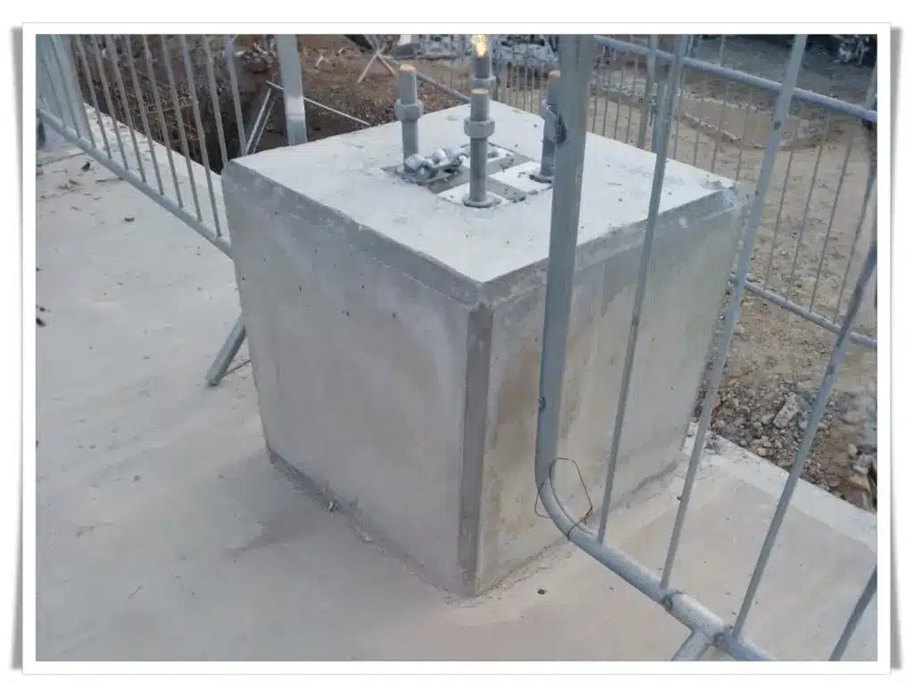
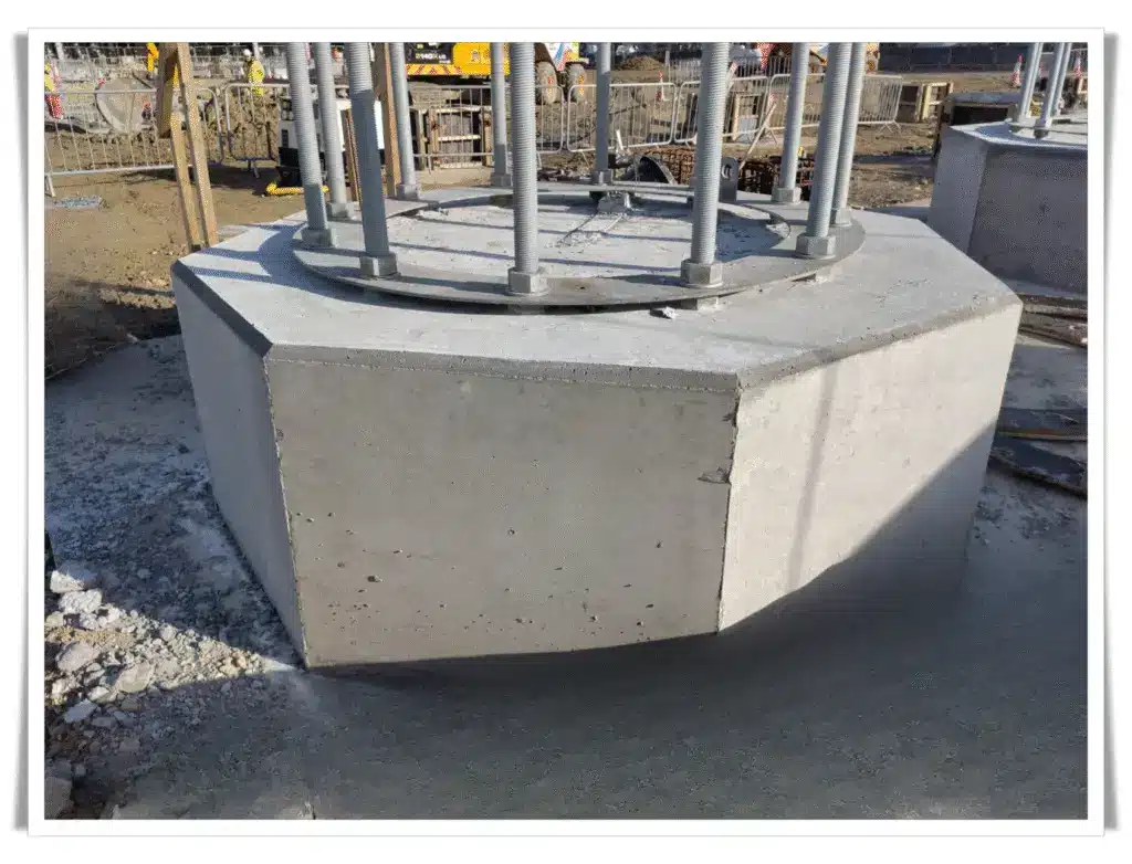
As a senior site engineer, I’ve overseen full-cycle survey operations—from initial setting out to post-construction as-builts—across commercial, industrial, and infrastructure projects. My involvement spans civil packages such as pile caps, plinths, retaining walls, and structural steelworks. Site complexities—tight access zones, layered construction interfaces, and multiple subcontractors—demand consistent survey control and real-time verification. I’ve made it my mission to establish reliability through precise control and responsive documentation.
Setting Out Anchor Bolts – My Methods and Tools
Using Robotic Total Stations for Precise Layouts
I rely heavily on 1" angular accuracy robotic total stations—my preferred model being the GeoMax Zoom95. This instrument enables single-operator workflows, offers auto-lock features in tight environments, and integrates seamlessly with control software like X-PAD Ultimate. It’s especially valuable when working within congested or high-rebar plinths, where speed and consistency are key.
Establishing and Validating Control Points
Control is everything. I implement closed-loop traverses to eliminate cumulative error and reinforce them with resection methods for large or irregular sites. Redundant measurements help validate every setup, ensuring every bolt set-out sits within a reliable coordinate framework.
Precision in anchor bolt setting out doesn’t begin at the bolt—it begins with your control points. These reference markers form the backbone of your entire site survey. If they're wrong, everything downstream is wrong too. Here's how a 1" angular accuracy RTS, when combined with closed traverse procedures, ensures bulletproof survey accuracy.
What Is a Closed Traverse – and Why Use It?
A closed traverse is a looped series of measurements between control points, where the final station closes back on the starting one or a known point. It allows surveyors to:
- Detect and correct measurement errors (both linear and angular).
- Validate that control points align accurately with the site’s design grid.
- Quantify misclosure and apply distributed corrections using least squares or Bowditch methods.
When working to sub-5mm tolerances for tasks like anchor bolt setting, this isn’t just useful—it’s indispensable.
How 1" Angular Accuracy Improves Traverse Reliability
A 1" (one-second) RTS offers extremely fine angular resolution—this is especially important when you’re measuring angles between long traverse legs.
Let’s break this down:
- An angular error of just 5 seconds at a 50 m leg could cause ~1.2 mm error at the far end.
- A 1" RTS reduces that to just ~0.24 mm, enabling you to maintain tight tolerances throughout the traverse.
Real-world impact: Over a four-leg traverse around a large slab foundation or industrial plinth, the cumulative error with a 5" RTS could be several mm—unacceptable for critical elements like anchor bolts. With a 1" RTS, you’re within target tolerances without guesswork.
Establishing a Control Grid You Can Trust
Here’s a step-by-step look at how I use a 1" RTS with closed traverse techniques in practice:
🔹 Step 1: Set Up Initial Known Points
Usually from a site benchmark or OSGB36/15 coordinates.
🔹 Step 2: Perform a Closed Loop Traverse
Using at least 4–5 total stations around the area of interest (e.g., the plinth, base slab, steel column grid), I measure:
- All angles between stations.
- All distances with EDM (Electronic Distance Measurement).
🔹 Step 3: Adjust the Traverse
Using software or manual methods (like Bowditch or least squares), I calculate:
- Angular misclosure.
- Linear misclosure.
- Apply adjustments to evenly distribute any detected errors across the loop.
🔹 Step 4: Validate Control
I resection from multiple points within the traverse loop to cross-verify internal consistency.
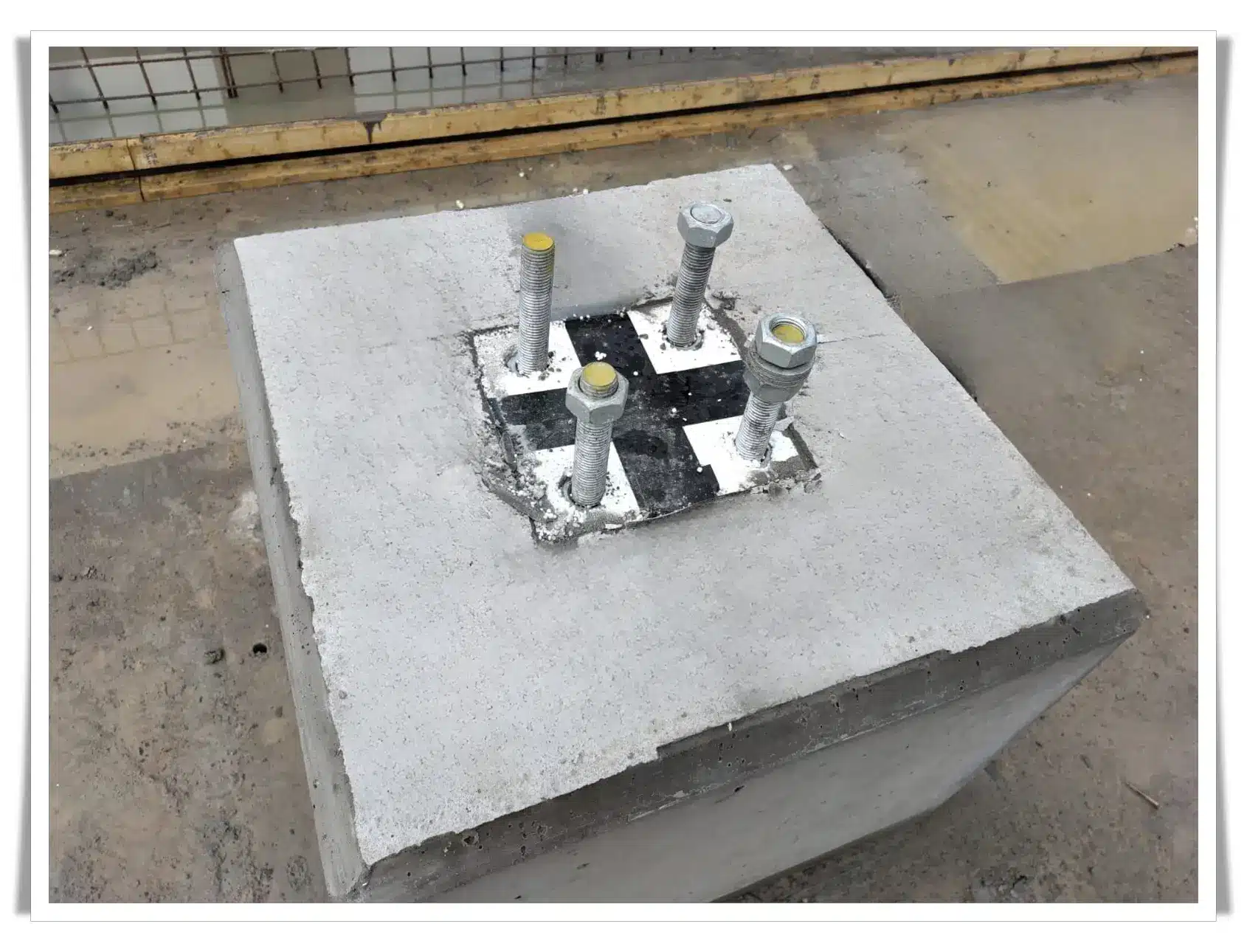
Anchor Bolt Setting Out from Verified Control
Once the control grid is validated:
- Anchor bolts are set out using polar coordinates from at least two control points.
- I stake them using a GeoMax Zoom95, mounted with a mini prism on a 0.5 m pole for low-clearance work inside formwork or baseplate sleeves.
- Because the traverse is solid and verified, I know the bolts will fall within ±2 mm of their design locations.
QA/QC and Documentation Confidence
Because I’ve used a 1" RTS and verified my control through a closed traverse:
- I can produce as-built reports with confidence.
- Survey data matches design coordinates in AutoCAD or Revit overlays.
- Engineers can use my outputs directly for baseplate fabrication, column erection, or clash detection.
With sub-mm accuracy backed by geometry, I eliminate disputes at the source—and demonstrate competence through data.
Overcoming Visibility Issues with Mini Prisms and Poles
Obstructions are common—shuttering, rebar cages, or site clutter often block line of sight. In such scenarios, I switch to mini prisms on short fixed poles or pointed prism poles, ideal for precise centring within shutter boxes or embedded sleeves.
Independent Verification of Subcontractor Works
Cross-Checking Against Construction Drawings
I always independently verify subcontractor layouts using design-issued CAD drawings and tolerance schedules—typically working within ±3mm for bolt locations. It’s not uncommon to find offsets caused by template misplacement or incorrect rotation.
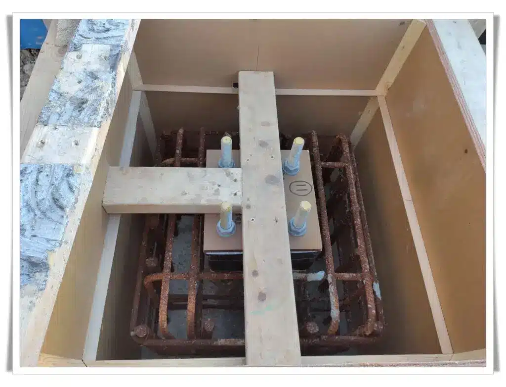
Validating Bolt Templates Before and After Pour
Before concrete is poured, I capture the XY bolt grid with offsets from fixed benchmarks. After pour and stripping of formwork, I return to do a post-pour re-check. One instance revealed a 12mm shift due to formwork movement—caught in time to adjust the steel column baseplates before erection.
Conducting Detailed As-Built Surveys
Surveying Before Formwork Removal
Before formwork is dismantled, I capture bolt centre coordinates using targeted mini prism setups—ensuring unobstructed, high-accuracy shots. These are cross-verified against the known template geometry.
Design vs Actual Position – Tolerance Interpretation
Using CAD overlays, I compare surveyed bolt locations against the design model. Industry standard tolerances hover around ±3mm depending on the structure type and contractual requirements. Any bolt beyond this range is flagged for review.
Data Export and CAD Integration
Once the anchor bolt coordinates are captured during the as-built survey—ideally with a high-accuracy instrument like a 1" robotic total station—the next step is to translate field precision into usable digital deliverables for the design and engineering teams. This is where data export and CAD integration becomes critical.
From Field to Office – Clean Data Export
Survey data, captured in the field via onboard software such as X-PAD Ultimate or similar, is exported in DXF or DWG format—industry-standard file types that integrate seamlessly with platforms like AutoCAD, Revit, Tekla Structures, or even Navisworks for coordination reviews.
Each point is typically exported with:
- Unique point ID (e.g., BOLT-C1, BOLT-D3)
- X, Y, Z coordinates
- Point description (bolt type, template ID, or as-built note)
- Optional: timestamp, instrument used, and surveyor initials (for traceability)
These files are structured to align with the project’s CAD layer conventions, making them plug-and-play for BIM teams and structural designers.
Overlaying the Data – Structural Comparison
Once imported into the structural layout, these points are overlaid against the design grid (usually established from Revit or DWG base files). This enables engineers and steelwork contractors to perform a side-by-side comparison of:
- Design intent vs actual bolt positions
- Any shifts in bolt grids (e.g., if formwork moved or templates warped)
- Elevation discrepancies where baseplates meet sloped or stepped slabs
Visual checks are enhanced using:
- Colour-coded deviation markers (e.g., green = within tolerance, red = out of tolerance)
- CAD annotations showing offset magnitudes and directions
- Leader lines or callouts indicating corrective actions needed
Bolt Position Deviation Histogram
To visualise how the as-built data compares to the design intent, I routinely produce a histogram chart showing bolt positional deviations across the surveyed area.
This chart quickly highlights:
- How many bolts fall within target tolerance (e.g., ±3 mm)
- The distribution of deviations (are they consistent or skewed?)
- Whether there's a systematic error (e.g., all bolts 5 mm east—suggesting control was off)
Here’s what a typical bolt deviation chart might look like:
| Deviation Range (mm) | Number of Bolts | Status |
|---|---|---|
| 0.0 – 1.0 | 18 | ✅ Excellent |
| 1.1 – 2.0 | 12 | ✅ Within tolerance |
| 2.1 – 3.0 | 5 | ⚠️ Acceptable |
| 3.1 – 5.0 | 2 | ❌ Out of tolerance |
| > 5.0 | 0 | ❌ Major issue |
In one project, this chart helped us justify remedial grouting on two baseplates and prevented unnecessary delays during steel erection.
Why This Matters: Engineering Adjustments Without Guesswork
Having the surveyed bolt coordinates digitised and overlaid in CAD gives structural and site engineers the foresight to:
- Modify baseplate hole positions before delivery.
- Pre-drill compensatory slots into the steel baseplate.
- Add grout pads or shim packs where Z-level deviations are found.
- Coordinate with steel erectors and crane crews in advance.
In essence, this level of integration eliminates reactive fixes, saving both time and cost.
Deliverables Typically Provided
- DXF/DWG of surveyed bolt positions
- CAD overlay showing deviation vectors
- Bolt deviation histogram or Excel summary
- Annotated PDF mark-ups for QA documentation
- Photos geo-tagged to each point (optional)
Tools, Systems & Documentation Practices
Coordinate Management with OSGB15 System
All site work adheres to the OSGB36/15 projection, critical for absolute positioning and multi-discipline coordination. Prism heights and instrument offsets are rigorously calibrated to maintain sub-centimetre accuracy.
Reporting – From CAD Mark-Ups to Photographic Evidence
Every step is documented: CAD screenshots of overlays, annotated photographs showing bolt identifiers, and PDF reports stamped for record. This transparent approach supports quality audits and handover documentation.
Lessons Learned and Recommendations for Future Projects
Reflecting on dozens of anchor bolt surveys, a few lessons stand out:
- Early involvement is crucial: Get surveyors engaged during formwork planning.
- Don’t rely solely on subcontractor templates: Always verify against drawings.
- Document everything: Even minor discrepancies can become legal issues later.
- Use technology to your advantage: Invest in robotic stations and smart software to reduce human error.
Tip: Standardise your bolt ID convention across teams to avoid mix-ups.
Conclusion – Precision is More Than Just Numbers
Anchor bolt setting out is one of those unseen foundations upon which entire structures depend. Precision here isn’t about ticking boxes—it’s about preventing future failures, enabling seamless construction, and upholding engineering integrity. In my experience, meticulous survey practice paired with the right tools and mindset transforms what could be a fragile process into one that’s rock solid—bolt by bolt.
Like this article?
Follow for more insights on professional surveying practice, CAD integration, and real-world site engineering methods from a U.K. construction veteran.
Resources & Recommendations
To ensure precision, compliance, and adherence to industry best practices in anchor bolt setting out and as-built verification, the following standards and technical resources are highly recommended. Each reference provides essential guidance on tolerances, survey accuracy, and structural alignment procedures relevant to U.K. and international construction practice.
- BS 5606:2022 – Accuracy and Tolerance in Design and Construction (BSI Guide)
A comprehensive British Standard outlining how to manage design and construction tolerances to maintain accuracy and mitigate on-site dimensional risks. - ACI 117.1R-14 – Guide for Tolerance Compatibility in Concrete Construction
A detailed American Concrete Institute reference offering best-practice recommendations for maintaining compatibility of tolerances across different construction disciplines. - Anchor Bolt Tolerances – ForConstructionPros Technical Article
An industry article explaining the practical implications of anchor bolt misalignment and how to achieve positional accuracy during installation. - EAD 330924-01-0601 – European Assessment Document for Cast-in Anchor Bolts
The official European technical document outlining performance requirements and assessment procedures for cast-in anchor systems. - AD 268 – Bolt Lengths (BS 5950-2:2001 Reference)
A concise advisory document from New Steel Construction covering bolt length requirements and thread engagement tolerances for steel structures. - RPSA New-Build Inspection & Reporting Standards v1.4 (UK)
U.K. standard for professional inspection and reporting of new-build structures, relevant for as-built verification and compliance documentation. - What an As-Built Survey Actually Tells You – AKN Engineering (UK)
An insightful explanation of as-built surveys, including their purpose, scope, and the tolerances typically assessed on construction projects. - As-Built Surveys – Encompass Geospatial (UK)
A clear overview of as-built survey methodology, positional accuracy requirements, and how these surveys validate construction quality. - Compliance and Quality Assurance Surveys – Castle Surveys (UK)
Example of professional QA survey reporting within U.K. construction projects, detailing real-world approaches to dimensional verification. - BS 4190 – Dimensions and Tolerances for Bolts, Nuts, and Screws (Historical Reference)
Though withdrawn, this classic British Standard remains a valuable reference for understanding dimensional tolerances and thread standards used in structural steelwork.